Radiation Resistance


|
Radiation Resistance
|
|
Related pages on Antennas , radiation and fields , mobile and short verticals My 2004 Dayton Hamvention Power Point presentation on Small Verticals can be downloaded here... DAYTON 2004. When dealing with small antennas, the main points to remember are:
How do we make a small antenna as efficient as possible?
The steps outlined above maximize radiation resistance and minimize loss. Let's look at the interaction between radiation resistance and loss resistance. Radiation ResistanceRadiation resistance is both the most useful and the least useful antenna-related term. Radiation resistance can easily be misused and rendered useless. This is because radiation resistance has multiple poorly-defined meanings. When a term has several nebulous meanings or uses, it is only natural that misuse or mixing of terms appear. Lack of a firm, single, well-accepted, definition allows the term "radiation resistance" to slip from one definition into another. This often results in well-intentioned, but totally erroneous conclusions, that seem to follow accurate, logical, thought! Common UsesThere are two commonly-used "correct" meanings of radiation resistance, and one totally incorrect use. The "correct" uses are:
Neither of the above definitions include loss resistances of any type! The moment loss resistance is included, we have a third commonly-used (but totally useless) definition. This definition, which includes losses, could be considered "incorrect" because it includes resistances that have nothing to do with radiation. The misused, or nearly useless, definition is: 3. The simple real (or resistive) part of an antenna's feedpoint impedance, wherever that feedpoint is in relationship to the radiating current maximum. The correct name for number 3's "radiation resistance" is actually the antenna feedpoint resistance. It is not radiation resistance at all! Of the above good or useful definitions, the first definition is most commonly abused through mistake. The second definition is an IRE definition (albeit a good one that never caught on). In every case, the second good definition, which is also the least commonly used, provides the most direct and useful answer. Examples of MisuseIn order to understand what is right, we sometimes have to learn what is wrong. Let's look at a few examples where radiation resistance is misused to give wrong answers. Folded MonopolesFolded monopoles provide the clearest common example of radiation resistance misuse. Quite often, in discussions of vertical antenna ground system loss, claims are made that multiple drop wires increase radiation resistance and lower earth or ground system losses. The justification is multiple drop wires, or a folded monopole element, increases radiation resistance. The increased radiation resistance reduces ground currents and ground losses. This concept is justified and/or rationalized through use of another commonly misused and abused formula: eff % = 100 * Rrad/(Rrad + Rloss) . In order to use the formula above, all losses must be normalized to the same point where radiation resistance is taken. Without doing that, the efficiency formula above does not work! Many articles, especially folded monopole articles, either ignore the fact that loss resistances must be normalized to the feedpoint, or authors are unaware of that rule. Let's look at what actually happens in a folded element, and use it to understand how the poor definition of radiation resistance causes efficiency misunderstandings.
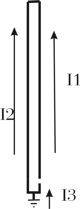
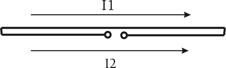
Consider the unipole to the left. Let's assume it is 1/4 wavelength tall. Let's assume we short or close the open gap and feed it as a normal 1/4 wave Marconi vertical with a feedpoint at the point where I3 is shown. I3 is ALWAYS the vector sum or in-phase combination of currents I1 and I2. With continuity through each leg, I1 and I2 equally share all of the ground current. This happens regardless of where the feedpoint is located in the lower portions of the antenna. With 1/4-wl height and with a reasonable element diameter, the radiation resistance (fed as a traditional monopole) would be about 36-ohms. Let's assume ground loss, normalized to the point where we measure I3, is14 ohms. Applying 500 watts makes I3 a current of 3.16 amperes. Power loss in ground resistance would be I^2R, or 3.16^2 times 14, about 140 watts. Feedpoint resistance would be 50 ohms. Feedpoint power, as a check, would be 3.16^2 times 50 ohms or 500 watts. With equal diameter legs, this current would divide and 1.58 amperes would flow in each upper leg at I1 and I2. Let's use the formula eff %= 100*Rrad/(Rrad+Rloss). We have 36/36+14 = .72 so the result is 72% efficiency, or 28% loss. 28% loss times 500 watts is 140 watts in ground losses. This matches the other method just above. Opening the gap and feeding as a folded unipole, half of the radiator current is in I1 while the other half is in I2. Current is halved to 1.58 amperes at the feedpoint and power remains the same. The feedpoint resistance now becomes 200 ohms. We can confirm this with I squared R, or 1.58^2 *200=500 watts. It all works out great so far! Now let's misuse the same efficiency formula, like Orr did in his Radio Handbook and others do in various articles. We have 200/200+14 = .9346 or 93.46 % efficiency. It seems by using the folded monopole element we have increased efficiency from 72% to 93.5%! We know we still have 3.16 amperes flowing as I3, and we know ground resistance is still 14 ohms (normalized to the point where I3 is measured). I-squared-R losses are 3.16^2 * 14 = 140 watts! We have exactly the same power loss in the ground. Let's transform the ground loss value that was normalized at 14-ohms where I3 is measured to the feedpoint by the same impedance multiplication as the feed resistance, or 1:4. We'd now have a normalized ground loss resistance of 4*14 = 56 ohms. 56 ohms of the 200-ohm feedpoint resistance is loss. Trying that same efficiency formula, we get: 144/144+56 = .72, or 72% efficiency!!! Now everything checks out fine. Radiation Resistance, most common mistakeMany people use the first definition of radiation resistance, the portion of the terminal resistance of the feedpoint responsible for radiation. Unfortunately they fail to normalize ground losses to the same point where the radiation resistance is taken! We can not use a formula that is based on everything being normalized to one point and not normalize to that point for every term in the formula! There is no change in efficiency when the NET radiator current remains the same and when net ground current remains the same. Even if used properly, in many cases, losses are external to the antenna system. These losses appear exactly as if they are due to radiation. For example, a Marconi vertical can be -5 dB down from theoretical due to losses out in the Fresnel region, or from local induction field dissipation, and not appear to have an abnormally high feed resistance. To know efficiency and field strength, we really must measure field strength! Using The Second DefinitionIf we use the second IRE definition of radiation resistance, where the effective current causing radiation is compared to power radiated, we find nothing changes. A folded dipole or monopole has the same radiation resistance as a regular dipole or monopole the same size, and a small loop has the same radiation resistance regardless of turns. The magic vanishes along with the incorrect definitions and perceptions. You can read about this in textbooks. The "Antenna Engineering Handbook" by Jasik in 3-13, 19-3, and in other sections uses correct definitions and descriptions. Quad's and other LoopsWe find the same efficiency misconceptions in articles about small loops and large quads. Authors sometimes assume, incorrectly, radiation resistance changes in a favorable proportion to loss resistance as feed impedance increases. What we really are doing is placing the feedpoint in series with a smaller portion of NET current causing radiation. The quad antenna has two current maximums, and the feedline only connects to one of them. With a large full-size quad element the pattern under some conditions will slightly change, but efficiency remains basically the same. With a small "magnetic" loop antenna, losses usually increase with more turns! This is why most commercial transmitting loops only have a single turn. Folded Dipoles Folded dipoles, like folded monopoles, are another example of a system where radiation resistance can have two significantly different values, depending on which definition is used. As with the monopole, the folded dipole only has half of the normal dipole current in each conductor. The sum of I1 and I2 is identical to a simple traditional dipole. Using the IRE definition of radiation resistance, freespace radiation resistance of a thin folded dipole is approximately 73 ohms. Using the less useful feedpoint resistance method, radiation resistance would be approximately 292 ohms. Some engineering books use the IRE definition, and clearly state a folded dipole has about 73 ohms radiation resistance, while other less-profession texts use the real part of feedpoint resistance. In amateur circles, the Coaxial Dipole (or Double Bazooka) misuses the formula eff % = 100 * Rrad/(Rrad + Rloss) to claim the coaxial dipole or double bazooka has gain over a regular dipole. This is one of the most abused formula in articles. Terminated Folded ElementsAnother abuse of radiation resistance is found in terminated antennas. Some manufacturers and authors claim a resistance can be inserted in series with one leg of a folded monopole or folded dipole, and the other leg fed. The usual arm-waving claim is the antenna isn't really resistor loaded, and that efficiency is very good because radiation resistance is high. Once again the claim is incorrect, and the root of the problem is not normalizing losses to the feedpoint. A large terminated rhombic is well-known to have poor efficiency. Rhombic gain is actually low compared to other antennas having the same sin/sin x antenna pattern, because rhombic efficiency is generally less than 50%. At least half of the power is consumed in termination and ground losses below the antenna. The actual gain may be reasonably high compared to a dipole, but not to other efficient antennas with the same half-power beam width. The typical manufacturing buzz-word is that terminated monopole and dipole antennas are "traveling wave antennas" and by some magic (that even large terminated rhombic antennas can't achieve) have broad bandwidth and very high efficiency. A rhombic focuses energy (that is not transformed into heat) into a narrow beam that has considerable gain, but if it sprayed the radiation around in a non-focused pattern, a regular dipole would win hands down. Throw a resistor on that dipole to smooth SWR variations, or on a vertical, and efficiency suffers. I listened to a station on 75 meters 600 miles away testing a Sommer T-25 vertical. He was 30 over nine using a dipole, and dropped to S6 with the vertical. The European he was working reported a similar change. By removing the termination resistor and base-loading the same vertical, a local Ham gained almost 25dB on 80 meters! When we abuse or misuse radiation resistance, we can invent all kinds of magical antennas. We can have CFA's, E-H antennas, fractal loops, terminated dipoles, small magnetic loops, and verticals with all sorts of magical claims. Few, if any, of the claims are ever correct. Any time we see a claim that efficiency changes a large amount because of a feed method change, or that an antenna makes exceptional efficiency without proper supporting field strength measurements, it should be a red flag. Increasing Radiation ResistanceRadiation resistance, at least under the useful IRE definition, can be defined by the following formula:
which would translate to:
Where He is the effective height center of accelerating charges that cause radiation. In other words, He is the effective height, expressed in fractions of a wavelength, of the distributed common-mode current in the structure. (Common-mode current is the vector sum of all currents, or the effective in-phase current at any point, or the current we would measure if we placed a giant clamp-on current probe around ALL of the conductors at that any given height.) He and As an example, a uniform current single conductor antenna has an actual physical height of 15.19 feet on 1.8 MHz, where one wavelength is 546.67 feet, the effective height is: 15.19/546.67= 0.0278 wl Since charges are distributed evenly throughout the structure the full height is used. The effective height is .027 wl, the same as the physical height. The height in electrical degrees is .0278 * 360 = 10 degrees We have a radiation resistance of:
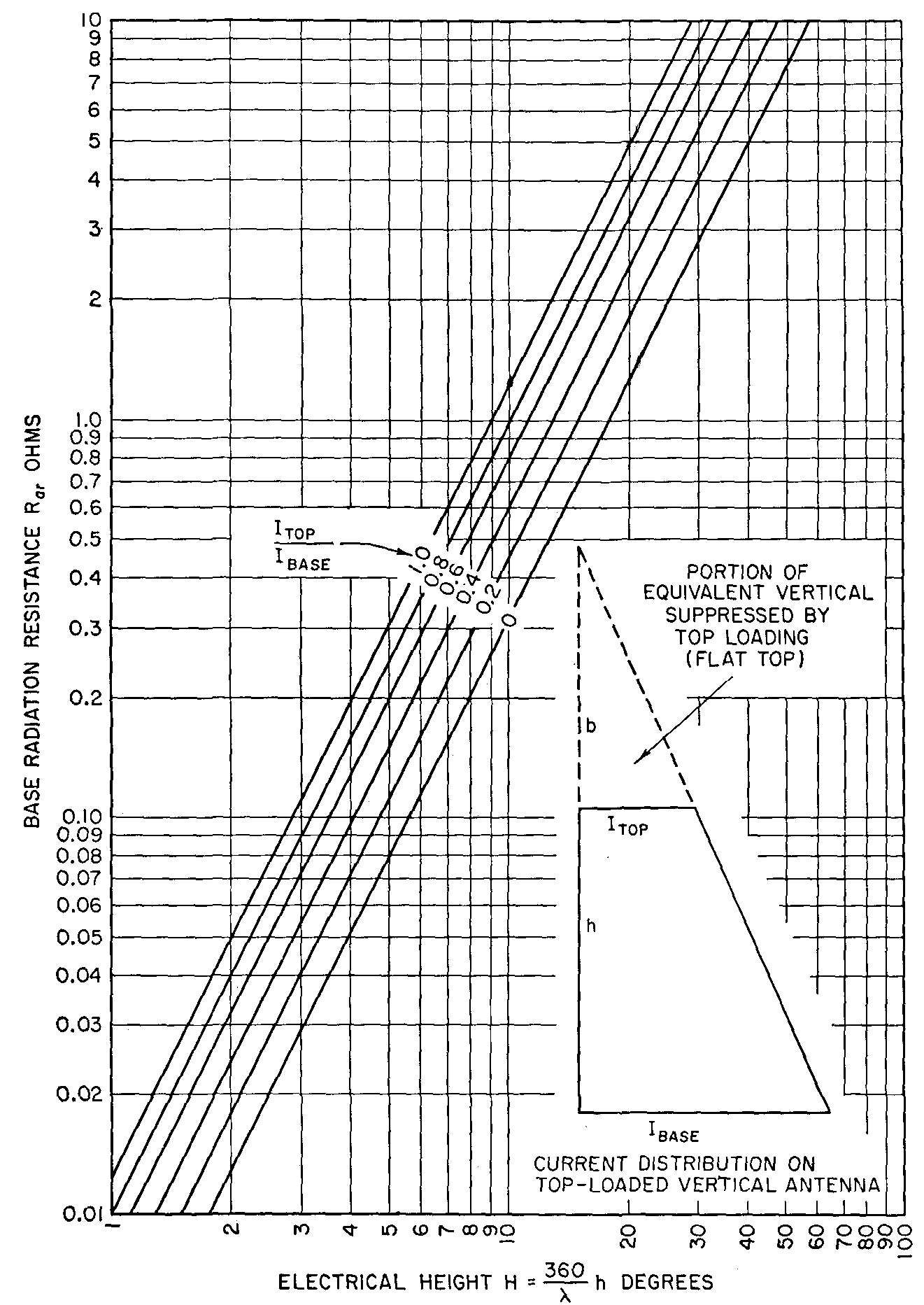
We can express this graphically in a chart, such as one found in the Antenna Engineering Handbook by Jasik:
Finding 10-degree height on the graph above, and following that line until we reach the crossing for unity current ratio, we see the ~1.27 ohm radiation resistance is in agreement with theory. Notice that the number of vertical conductors does NOT enter into the equation! This is the absolute maximum possible radiation resistance we can obtain for a given radiator height from tip-to-base spatial distance (height). Non-uniform CurrentRadiation resistance is purely a function of the effective current distribution and height of the radiator, and is limited by height (spatial length)! Current throughout the antenna will not remain uniform if we reduce the size of the flat-top or hat. Current will become zero at the very top with no hat, and 100% base loading. In this case, with no change in height, radiation resistance will be approximately 1/4th the value of the uniform current example. The result is exactly like a 50% reduction in effective element height. If we follow the 10-degree line to the intersection point with 0 top current, we find radiation resistance to be around .32 ohms. 1.27 ohms, the radiation resistance for uniform current, becomes 1.27/4 or .3175 ohms. If we stay on the uniform current line, we find that .3175 ohms would be the radiation resistance of a 5-degree monopole with uniform current. EfficiencyIt often helps to look at the extremes, so we can get a feel for the effect of changes. Let's look at the poor ground extreme and assume we have system losses, normalized to the current maximum, that are many times the radiation resistance. This would be the case for a short 160 or 80 meter mobile antenna. In such a system radiation resistance would dominate any change that would affect efficiency. Current distribution would mean everything to efficiency. Assume we have a base loading coil, either good or poor, and a thin mobile whip above the coil. Efficiency would increase by a factor of approximately four times by installing a capacitance hat with several times the distributed capacitance of antenna conductors below the hat. Moving the coil would have little or no effect on efficiency. A six-foot antenna with a large hat would be electrically equal to a 12-foot antenna without a hat. This is why very poor inductors used on antennas in mobile shootouts, with large hats, equal or beat very large high-Q coils in similar height antennas that do not have large hats. One case in mind was a Hamstick lash-up in a mobile. The Hamstick, a notoriously poor efficiency antenna for 75-meters, soundly trounced Bugcatcher antennas when a large hat was added to the Hamstick. Moving the coil up on the antenna has the effect of making current below the coil uniform, but without a hat current above the coil is a triangular taper that reaches zero at the element tip. The effective height of the area above the coil is 50% of actual height. If we add a large hat at the bottom of the whip, current in the whip is actually reduced! At the same time, we change nothing below the coil. The effect of adding a large hat below the whip is to reduce the effective height of the antenna, when considered as a percentage of physical height. Radiation resistance and efficiency is generally reduced by adding a hat just above a coil, even if the hat allows us to use a smaller coil! Adding a large hat at either end of a coil also reduces coil Q, since a large portion of the hat capacitance directly shunts the inductor. Shunting an inductor with capacitance reduces the number of turns required, but it increases circulating currents. Increased circulating current increases loss, even though less copper resistance is used in the inductor. ConclusionWe can reach the following conclusions:
This page has been visited
©2000-2004 W8JI
|