Related pages:
Sleeve baluns Balun and Transformer Core Selection 4:1 Balun Analysis Verticals and Baluns Antenna Tuner Baluns Common mode current Common-Mode Noise toroid balun winding Steel wool balun
Skip down this page to actual dipole measurements
| Note: Many authoritative articles and technical information sources on balun design ignore voltage, focusing only on current. Focusing only on current is a serious oversight that can result in defective system design. Equal currents alone do not assure balance, and SWR is not a confirmation of proper system operation. Consider this: All systems, both balanced and unbalanced, have exactly equal and opposite currents in each conductor when properly functioning. VOLTAGE is what ultimately determines balanced or unbalanced line or port design.
|
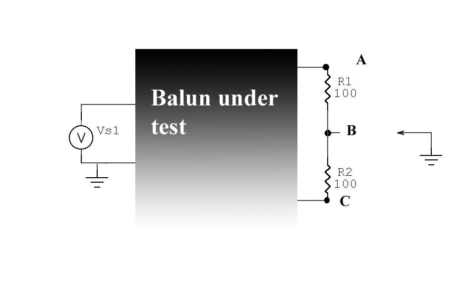
Balance Quality Test
We can test balance quality of a balun by moving a ground (common with signal source) to points A, B, and C and watching voltages or currents in the load. The best balun would have the least change in input SWR or current through R1 and R2 as the ground is moved.
R1 and R2 should be selected to equal design load impedance.
The same test above can be used, at high power, to roughly evaluate the power handling of the balun. The balun should not overheat at full power in a worse case condition for output jumper position. Heating limits in an HF balun, regardless of load impedance, is almost exclusively due to losses in the core. This is true for any type of balun in the real world. Do not confuse heating with flux-saturation of magnetic materials. Flux saturation does not necessarily cause heating, it simply means the core cannot carry any more flux and any additional current causes a reduction in inductance. Virtually all HF cores heat from the loss tangent of the core. The loss tangent causes the core impedance to appear as a complex combination of resistance and reactance. The resistive part represents the dissipative characteristics, while reactance is lossless.
All baluns, even transmission line baluns, will have significant flux in the core with real-world loads. This flux density is the primary loss or heating mechanism in a balun.
See 4:1 balun page for an analysis of winding common mode currents, which can be represented by voltages across the winding.
Impedance and SWR Test
This page shows measurements of various baluns and how various baluns compare.
Choke Impedance
This data shows the common mode impedance of the balun. In general, the highest impedance at the operating frequency or over the operating frequency range is desirable. This impedance isolates the antenna from undesired signals on the feedline shield, and prevents antenna terminal voltage from exciting the feedline with unwanted currents. Common mode impedance is directly related to the care in design and construction.
Pay particular attention to the impedance peak in air-core baluns. For narrow-band applications they make excellent baluns if load common mode impedance is not capacitive.
Unfortunately common-mode impedance is all over the place, as this Smith Chart plot shows:
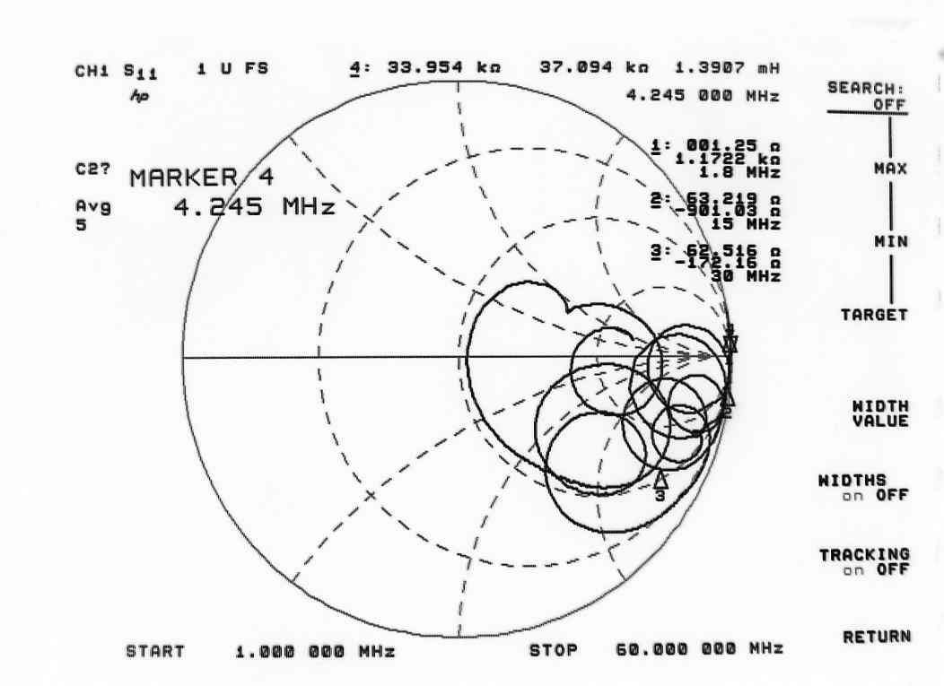
The air-core balun is good only for a three or four-to-one frequency range, unless you pick a winding style and size that places unwanted series resonances outside desired bands, and is only good where common mode impedance is inductive or the same sign as the balun's common mode impedance. If we are not careful with system design, an air-core balun can make system balance worse!
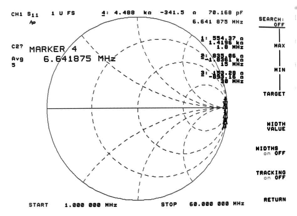
In contrast a good core-type balun looks like this:
SWR
The lowest SWR is desirable, although any mismatch can often be compensated by adjustment of antenna dimensions. This SWR mainly comes from incorrect wire impedance inside the balun. It may be caused by excessive length of internal leads, or incorrect cable or winding impedance inside the balun. It generally is a construction related problem.
Measured SWR and Choking Impedance
The following data is measured using a currently certified network analyzer with low capacitance test fixture:
| Centaur | DXE | W2DU(1) | W2DU(2) | Force 12 | Scramble | Solenoid | W2AU volt | ||
| Choke Impedance | Note 2 | ||||||||
| R+X@1.8 | 84 129j | 554 1.4k j | 378 617j | 230 325j | 169 286j | 1.67 245j | 1 +1.18k j | .488 5j | |
| R+X@15 | 3.76 2.7k j | 835 -1.84k j | 727 -611j | 761 -10j | 883 -105j | 11.97 -850j | 62 -895j | 1.36 42j | |
| R+X@30 | 143 -729j | 153 -893j | 284 -440j | 610 -296j | 538 -381j | 73 162j | 68 -168j | 8.2 68j | |
| Max Z@F | 17 MHz | 6.65 MHz | 7.16 MHz | 15.3 MHz | 13.24 MHz | 6.42MHz | 4.25 MHz | 60 MHz | |
| R+X at max Z | 5.87k -943j | 4.5K -340j | 1.3K -13j | 770 -20j | 914 2.25j | 42.7k 0j | 34K 37K j | 75 286j | |
| Min Z@F | 27.68MHz | 11.7Mhz | |||||||
| R+X at min Z | 10 -2j | 198 -252j | |||||||
| SWR | |||||||||
| F SWR=1.25 | 6.8 MHz | 65 MHz | 21.15 MHz | 20.2 MHz | note 1 | note 1 | 20.9 MHz | ||
| 1.8MHz | 1.07 | 1.02 | 1.03 | 1.03 | 1.43 | ||||
| 15MHz | 1.58 | 1.04 | 1.17 | 1.18 | 1.2 | ||||
| 30MHz | 2.16 | 1.08 | 1.37 | 1.39 | 1.35 | ||||
note 1: SWR not measured because construction and cable type affects SWR
note 2: This is a W2AU voltage balun. It is only shown as a example of poor shield isolation offered by voltage baluns if the antenna is not perfectly matched to the balun with the feedline exiting the balun at right angles. This type of balun is unsuitable for non-symmetrical systems such as off-center-fed antennas, verticals, or antennas with the feedline paralleling the antenna (even at a fairly large distance).
The W2DU baluns were manufactured by Unidilla. (1) is a Maxi balun and 2 is a 10-40 meter model.
The DX Engineering balun is the dipole balun type DXE-BAL050-H05-P
The scramble-wound choke was about 20 feet of RG8X in a six-inch diameter "bundle".
The solenoid balun was about 60 feet of RG-8X on a 4" PVC thin wall drain pipe coated with rubberized roofing tar.
Power Dissipation and Feedline Common-mode Current Estimates
Note: This section revised 1/2/2003 to correct model error. Please report any other errors to me!
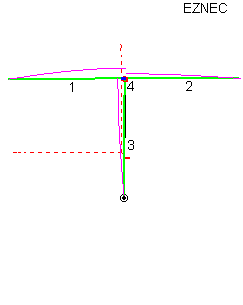
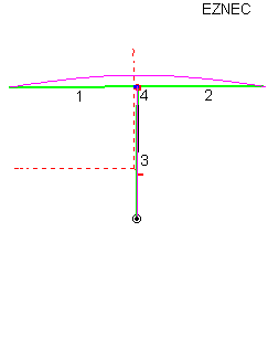
Balun power dissipation is estimated using Eznec to simulate a perfectly balanced dipole.
Here is a copy of the model used:
Please be aware I made no special effort to create a "bad antenna" other than I intuitively understand what the worse case condition of feedline length would normally be and I selected that length. I dropped the wire representing the feedline vertically from the center of a perfectly balanced dipole, and made that wire 1/4 wl long.
Here is a view of the model with no balun:
SWR is 1.46:1 power is 1500 watts
Currents at 1500 watts are approximately:
5.65 amperes into wire 1
2.63 amperes into wire 2
3.73 amperes into wire 3 (coaxial cable shield)
Using this model (a 135 foot high 160-meter dipole) we can add each of the balun impedances in the coaxial cable shield and estimate feedline current and power dissipated in the balun:
| Centaur | DXE | W2DU(1) | W2DU(2) | Force 12 | Scramble | Solenoid | W2AU |
| 0.90 amp | 0.12 amp | .25 amp | .47 amps | .57 amps | .87 amps | .16 amp | .4 amps |
| 69 watts | 8.5 watts | 25 watts | 51 watts | 55 watts | 1.3 watts
(26w TL loss) |
.03 watt (74w TL loss) | 34 watts |
From this we can see the following:
- Adding more beads is very inefficient. W2DU(1) has about twice the beads as W2DU(2), yet it has 53% of the current and 49% of the power dissipation! This does increase power rating by a factor of four, but it is still too low to prevent balun heating.
- The solenoid has (by far) the lowest choking or balancing power loss, but it is 60-feet of RG-8X wound on a 4" diameter form in a single layer. It adds transmission line loss of 74 watts, but since the area is so large it will not overheat.
- The scramble wound balun has inadequate impedance since wire length is only 20 feet. It has low loss, but it really isn't acting like a balun (at 6.5 MHz it would be super, having 42K ohms of impedance).
- Of the baluns above, only the DXE, scramble wound, and solenoid would not be overheated in normal operation for continuous Morse CW transmissions.
Perspective of Heat
Think about the heating this way. Imagine you had a 60-watt light bulb. Nearly all of the applied power is turned to heat, and the surface area of the bulb and conduction through the base radiates that heat. Would you hold a 60 watt light bulb?
Now picture a balun core with a surface area a fraction of the size of the light bulb. This core area is enclosed in a case that often has poor thermal conductivity.
- The large air-core baluns mainly produce heat from transmission line losses.
- W2DU and other style baluns mainly have CORE losses. Transmission line losses are negligible since the transmission lines are very short.
Currents
Every ampere of current not going onto the cable shield goes to the dipole's shield-fed leg! The total is not the exact sum, because of phase differences. Here is a view of currents in the dipole with the DXE balun:
Currents are:
Wire 1 4.52 amperes
Wire 2 4.52 amperes
Wire 3 .12 ampere
Remember power radiated increases by the square of current. The feedline shield current is now .12A compared to 3.73A without a balun! The feedline radiates about .1% of the power it radiated without a balun. While pattern distortion on transmit may not hurt, the feedline radiation probably aggravates RFI and allows noise to couple into the antenna when receiving.
Remember this model is worse case in the NO BALUN condition. This does not mean every system or most systems will be this bad. This example was only intended to show how bad balance can be and how much power baluns (even with a matched load) can dissipate!
Ladder Line Voltage and Current tests
The data below was taken with a half-wave 80 meter doublet about 120 feet or so above ground. This doublet is suspended between two towers and is suspended by rope for at least 30 feet from each tower. Nothing is within 100 feet of the doublet. Feedline is a vertical drop of Wireman "heavy duty" ladder line, twisted to maintain electrical balance and reduce wind oscillation.
In the table below, "D C" is a standard dual-core two-transmission line balun. It has two independent magnetic paths for each balun transmission line.
Look at how terrible balance is on a single-core 4:1 "current balun" below. A 4:1 single-core "current balun", as presented in "Baluns and Unun's" and used in some commercial designs, forces a system into gross voltage unbalance. It is not a balun. This is what happens when we offer a balun design without understanding or measuring balance.
|