Summary
Military Messages often need to be transferred over low bandwidth networks, in particular HF Radio and Satellite Networks. Scenarios requiring this and protocol descriptions are given in the Isode whitepaper [Military Messaging over HF Radio and Satellite using STANAG 4406 Annex E].
Isode provides ACP 142 and STANAG 4406 Annex E as a part of its M-Switch X.400 product. This paper describes Isode’s approach to implementing these protocols, and how this addresses basic and advanced operational problems, management approaches and integration with other components as part of a larger solution.
Solution Overview
The following diagram illustrates how the relevant core components of M-Switch X.400 operate. The central part of an MTA is the queue of messages in disk. Reliable store and forward messaging provided by an MTA works by receiving a message and reliably storing it in a local queue. The message can then be sent onwards (or delivered locally) and then it is removed from the queue. Even where a message is only held for a few hundred milliseconds, this reliable storage is central to MTA function.
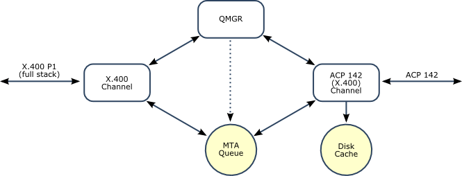
M-Switch X.400 has a queue manager process ("QMGR") that is responsible for scheduling and control of MTA operations. QMGR interacts with "channels" that do the work of sending and receiving messages. The X.400 Channel is used for handling "full stack"
ACP 142 and Annex E support are provided by a new ACP 142/X.400 channel that provides support for transferring X.400 P1 over ACP 142. This fits cleanly into the M-Switch functional architecture.
ACP 142 Channel Operation
The ACP 142 channel is a static process, which listens on a UDP port for incoming packets. This is essential, as incoming data may arrive at any time. The ACP 142 channel can access the MTA queue, and it also has its own disk cache that contains information that will optimize performance and allow correct operation in the event of a system restart. In particular:
- Status of all transfers (send and receive).
- Pre-computed data packets to send.
- Received data packets from partial transfers.
The ACP 142 channel will gather incoming packets, and report transfer status to the QMGR. When a complete message is received, it will be submitted into the M-Switch queue. When a message is to be routed over ACP 142, the QMGR will instruct the ACP 142 channel to process the message, which will be in the MTA queue. The ACP 142 channel will then pre-compute the data packets and send the message. The ACP 142 channel will inform QMGR of transfer status, and update information in the MTA queue when needed.
Configuration Management
Isode's approach to configuration management is to hold information in a directory, as illustrated below. In most deployments, a directory server such as Isode's M-Vault will be operated on the same server as M-Switch X.400, and this can be considered to be a part of M-Switch X.400. Directory based configuration allows for secure client/server configuration management, and facilitates sharing of configuration information between multiple MTAs.
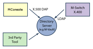
M-Switch X.400 and the ACP 142 Channel access the directory using LDAP (Lightweight Directory Access Protocol).
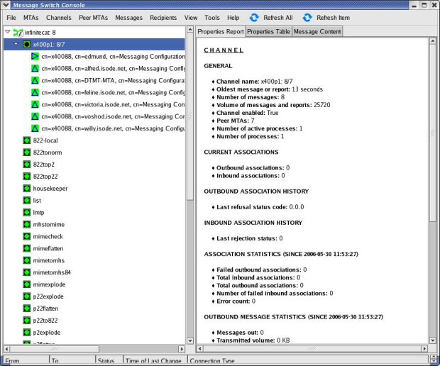
Isode provides GUI management of M-Switch X.400 using its MConsole product. This includes configuration of Annex E and ACP 142 configuration. The screenshot below shows an X.400 MTA, set up for military use (STANAG 4406).
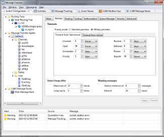
Click to show/hide detail
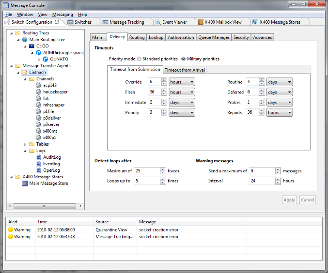
This includes configuration of Annex E and ACP 142 configuration. MConsole accesses the directory using X.500 DAP (Directory Access Protocol). DAP is used, as this is mandated in some military environments, and DAP supports security features not available with LDAP.
Isode publishes the directory schema used for its configuration, so configuration changes can be made by third party directory clients. This allows for full configuration management to be handled by different tools, or for selected changes to be made by specialized tools. The benefit of both of these options is explained later.
Operational Management
The following diagram illustrates the M-Switch X.400 operational management structure. The QMGR process is at the centre of operational control. QMGR interacts with the ACP 142 channel for both incoming and outgoing messages. When a message needs to be sent over ACP 142, QMGR requests "start transfer" to the ACP 142 channel, which will then begin
QMGR has the option to pause or abort transfer of messages. This can be in response to specific operator control, as a consequence of QMGR intelligent scheduling, or in support of general events such as "minimize"
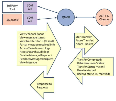
The ACP 142 channel will periodically report to the QMGR the state of transfer of both inbound and outbound messages. This will ensure that QMGR is aware of the status of all partially complete inbound and outbound transfers.
Management applications interact with the QMGR using the Isode SOM (Switch Operational Management) protocol. Isode provides 'C' and Java client APIs to SOM, to enable third party management applications to work with QMGR. Isode provides the MConsole GUI, as a part of M-Switch X.400 which allows operators to view message and queue status, and perform control operations, such as pausing transfer, requesting non-delivery, and redirection of messages. The following screenshots show of the capabilities of MConsole.
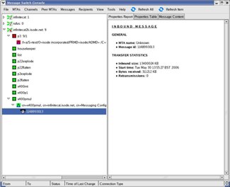
Click to show/hide detail

This first screenshot shows a message arriving. As the message has not been decoded, only basic information is available.
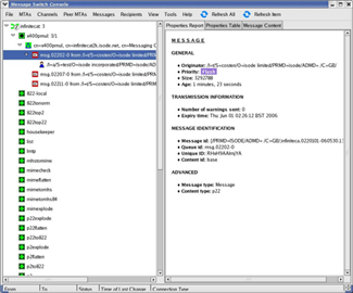
Click to show/hide detail
This screenshot shows a queue of messages for Annex E / ACP 142 delivery, with message-level status and priority.

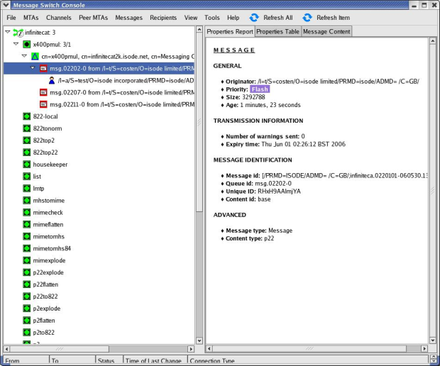
Click to show/hide detail
This screenshot shows a queue of messages for "full stack" X.400 P1. Note that this gives a very similar view – management
Audit, Tracking and Statistics
M-Switch X.400 records its activity into an audit log. These audit logs are processed and placed into an ODBC audit database. Isode publishes the schema of this audit database, so that third party applications can analyze the data, for example to generate reports.
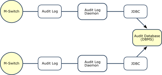
Isode provides a number of applications based on the audit database, in particular to enable message tracking, and to provide statistics.
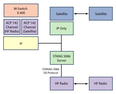
Network Support
M-Switch X.400 supports ACP 142 over two types of network:
- IP. This is important for general purpose deployment and in particular for use over Satellite.
- STANAG 5066. This is the interface to HF Radio.
Messaging Integration Points
Isode’s management architecture is client server, using open protocols where possible. Where Isode proprietary protocols are used, Isode provides client APIs for external integration. In particular:
- Configuration management is all handled in the directory, with published schema, so that external applications can manage configuration.
- Operational management uses the SOM (Switch Operational Management) protocol, for which Isode provides client APIs.
These APIs have been used by several Isode partners to produce integrated applications. Two are of particular interest for military deployments.
Insider Technology’s Sentra product provides advanced integrated management for messaging applications. Sentra makes use of SOM, LDAP, and analysis of Isode audit logs to provide a range of advanced management functionality. Sentra can be used to provide an integrated management view onto Isode M-Switch X.400 and onto Microsoft Exchange.
Boldon James are providing an integration of M-Switch X.400 and its Annex E/ACP 142 capabilities with Microsoft Exchange. This provides a tight integration between M-Switch X,400 and Exchange using Isode’s X.400 Gateway API. Configuration is stored in Microsoft Active Directory. Management is provided with a GUI that is closely integrated with Microsoft Exchange management (using Microsoft Directory management APIs and SOM), to provide a solution that will be straightforward for Exchange administrators to handle.
Benefits of the Integrated ACP 142 Architecture
A key Isode design decision is to tightly integrate ACP 142 with M-Switch X.400, as opposed to an ACP 142 implementation that is decoupled from the core MTA with a separate queue. This has a number of advantages:
- ACP 142, Annex E and X.400 have closely related functionality, and close coupling gives a more efficient and robust overall implementation.
- Configuration of ACP 142 parameters, can be naturally associated with the equivalent X.400 MTA components in a single directory location.
- Operational management can be integrated. A decoupled ACP 142 implementation will lead to two queues, with a message being present in both queues at the same time. The two separate queues need to be managed, and will most likely have different management abstractions.
These advantages can be clearly seen from the Isode configuration and operational GUIs, illustrated in earlier sections.
Handling Multiple Communication Channels
The paper so far has primarily considered use of a single constrained bandwidth communication channel. This section shows that many real deployments have multiple communication channels, and explains how the Isode products deal with this.
Scenarios and Requirements
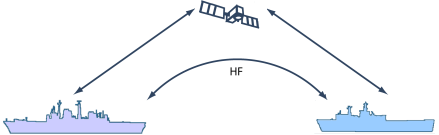
A ship will typically have two or more communication channels: HF Radio and Satellite. The combinations in use will depend on threats:
- Both channels in EMCON.
- Both channels active.
- One channel in EMCON. Typically Satellite channel will be in EMCON, because it has a stronger signal and is more visible. However, the "pencil beam" nature of the satellite and location of threat may lead to HF channel in EMCON and satellite active.
When both channels are open, use of Satellite may be preferred (higher bandwidth) or use of HF radio (lower cost), or a more complex preference dependent on messaging load.
With a headquarters unit, the EMCON status is simpler (as it would never be in EMCON), but there may be many more channels, for example to support multiple satellites with different ships reached through different satellite services. Other shore based systems, such as Special Operations could be in EMCON. Isode enables this with its multi-channel architecture.
ACP 142 parameters, such as transmission rate and retransmission timers cannot be tuned.
Configuration can be managed at the MTA level, by making use one channel for each communication channel. ACP 142 parameters can be tuned appropriately for each communication channel.
M-Switch X.400 routing can be used to select an appropriate channel for each recipient. In the event of needing to change channels while messages are queued, this can be handled by routing table modification, followed by reprocessing the queue. This will cause transfers on the first channel to be aborted, and then the messages will be moved to the other channel and queue.
Multi-Hop Routing
The initial scenarios showed situations where a message needs to be sent from TIA to LMTA and then on to another LMTA. This multi-hop routing can be important where there is not direct connectivity from TIA to an LMTA. Isode’s directory based routing is based on RFC 1801 “MHS use of the X.500 Directory to support MHS Routing”. RFC 1801 defines the concept of “routing tree”, which is routing information shared by one or more MTAs. Use of multiple routing trees enables complex multi-hop routing to be configured, while still allowing common routing information to be shared between MTAs. This section shows how various approaches to deploying Isode’s routing can be used to support different scenarios.
Isolated Directory Routing
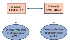
In this basic scenario, each MTA has a directory that holds routing information for each MTA. This might be considered a similar model to each MTA making use of local routing tables. The directory is a local system to the MTA.
This approach will often be a sensible approach for managing large LMTAs and TIAs, so that routing can be configured locally, without any need for directory traffic between the servers
Shared Routing for a TIA
An alternate setup is for two MTAs to share routing information in single (logical) directory. This configuration has the advantage of needing to manage routing information in one place. For resilience, a directory server will generally be run on the same server as each MTA. As the routing information is the same for both MTAs, the configuration will be replicated using X.500 DISP. This will give efficient incremental changes, and will generally be set up for on demand replication.
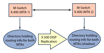
This approach would be suitable for a TIA implemented in a distributed manner with multiple MTAs having shared configuration. Managing common configuration in a single location is an important advantage of a directory server approach.
Remote Configured routing for a small LMTA
The example below shows a third variant, where MTA 1 and MTA 2 have independent routing configurations, but both configurations are mastered and managed on the directory server associated with MTA 1. The configuration for MTA 2 is replicated onto the directory server associated with MTA 2.
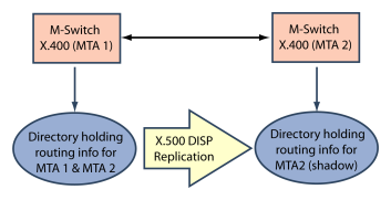
This approach will be sensible where MTA 2 is a small unit, where the local staff do not have sufficient skill or time to manage the routing configuration. For such a unit the routing configuration is likely to be fairly small and stable. In the event of changes, these will be made remotely, at a location where there is skill to handle the updates. Then the changes will be replicated when there is network availability and bandwidth.
Conclusions
This paper has summarized the architecture of Isode’s implementation of STANAG 4406 Annex E and ACP 142 technologies, how they are used to support military messaging, and Isode’s implementation of these technologies as a part of its M-Switch X.400 product. It has also shown how HF Radio and Satellite connections are supported. Isode’s architecture provides strong management capabilities and deployment flexibility.