Do you truly understand the SDR concept?
 A lot of magazine and articles have already covered
the principles of software defined radio. Most of them contain mathematical
equations which require a greater level of math. Certainly, without math there
would be no SDR, but I believe, that the concept of SDR can also be explained
without. Let me show you the SDR concept from a different point of view!
A lot of magazine and articles have already covered
the principles of software defined radio. Most of them contain mathematical
equations which require a greater level of math. Certainly, without math there
would be no SDR, but I believe, that the concept of SDR can also be explained
without. Let me show you the SDR concept from a different point of view!
Fundamentals: The three radio components
Independent of what kind of radio we are talking, a radio can always be broken down into three fundamental components:
- RF
Part
- Signal
Processing
- User
Interface
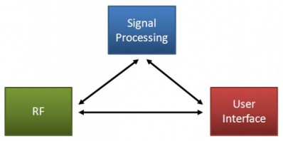
All three components interact with each other.
 The
RF component transforms high frequency signals into baseband signals or
vice versa. Parts of the RF component are filters, mixers, amplifiers,
oscillators, etc.
The
RF component transforms high frequency signals into baseband signals or
vice versa. Parts of the RF component are filters, mixers, amplifiers,
oscillators, etc.
 The baseband signal is processed / generated in the Signal
Processing component. In this component we will find functionality taking
charge of modulation, demodulation, NF filtering, noise reduction, etc.
The baseband signal is processed / generated in the Signal
Processing component. In this component we will find functionality taking
charge of modulation, demodulation, NF filtering, noise reduction, etc.
 The
User Interface (UI) is the command and control unit of the radio. It’s
the frontend to the (human) operator. The user interface might consist of
buttons, knobs, LEDs or just a PC screen.
The
User Interface (UI) is the command and control unit of the radio. It’s
the frontend to the (human) operator. The user interface might consist of
buttons, knobs, LEDs or just a PC screen.
The classic radio
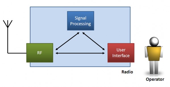
The classic radio is the kind of transceiver which we have in our shacks. It might be a FT1000MP, an IC706 or a Drake TR-7, just to mention a few of them. Over the last decades, the features and user interfaces have slightly changed, but the concept has remained the same: All-in-one-box.
All components are integrated in a single housing. With the increasing level of integration (and use of digital technologies) the physical dependency between the components increased as well. Even if some transceivers come with detachable control units (user interfaces), they are not interoperable with interfaces from other vendors. The schematic below illustrates the dependencies which come with this “All-in-one-box” concept of our today’s transceivers.
The SDR approach
As the classic radio, the software defined radio consists also of the three fundamental components RF, Signal Processing and User Interface. However, the tremendous difference is the physical and logical independency between the three components.
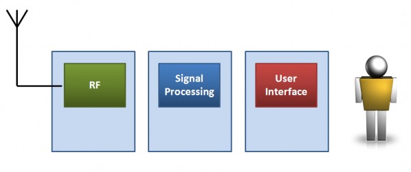
Physical Independency means that each of the three components can be realized in an individual housing. There is no reason why the components would need to be located at same site. Geographically they could be easily separated by 10.000 miles or more without any degradation in performance.
Logical Independency means that each particular component can be designed and changed without affecting the other components. Especially the digital domain allows us to have various independent instances of the same component.
It must be admitted that the enabler of the Software Defined Radio concept are standardized interfaces and protocols (USB, Firewire,TCP/IP..etc) as well as our speedy PCs with Internet connection. Do you remember that just a decade ago we were dreaming about having all that available once a day?
Maybe due to the unavailability of these standards and technologies commercial radio manufactures couldn’t produce what we were dreaming about 10 years ago – but on the other hand I suspect that they never had (and still don’t have) the interest to adopt to common (open) standards. The best examples are the various transceiver interfaces (CAT) and microphone jacks.
Enough theory – let’s have a look onto some real world examples how the SDR concept is already applied to!
Softrock with PC
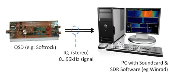
At the moment, this is worldwide the most common SDR setup. The antenna is connected directly to a Quadrature Sampling Detector (QSD) like the famous Softrock. The QSD mixes the RF signal into a baseband signal. The complex baseband (I/Q) signal is fed into the soundcard of the PC where the signal is digitalized. Signal Processing is performed by the PC. The user selects through the user Interface (here: Keyboard, Mouse and Screen) the settings like frequency, mode, filter bandwidth, etc.
Using our three components, the schematic would look like this:
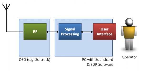
The “radio” consists of two physical components, the QSD and a desktop PC. The only connection between the QSD and the PC is a stereo audio signal. There is no physical dependency. The QSD could be exchanged (e.g. a softrock receiver against a Genesis) without affecting the signal processing or the user interface at all. On the other hand, if a new digital mode (e.g. PSK31) shall be decoded, this software update can be installed without affecting the RF component at all.
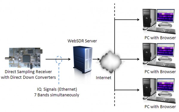
WebSDR with Various WebClients
Have you already
seen Pieter-Tjerk, PA3FWM’s WebSDR
which he operates from the University of Twente in
the Netherlands? Pieter built up a Direct Sampling Receiver consisting of a
very fast Analog Digital Converter (ADC), followed by a Field Programmable Gate
Array (FPGA) where several Direct Digital Down
Converters (DDC) are implemented to (basically) filter out the 7 desired bands.
The receiver sends the I/Q signal of 7 bands, with a bandwidth between 150kHz and 1,2MHz via Gigabit Ethernet to a
local Server. This server is the interface between the receiver and the users.
A user connects through the web browser to the server where the server provides a spectrum scope for each band. Within the spectrum, the user can select the desired frequency, mode and filter bandwidth, and receives instantly the audio signal. The I/Q to Audio conversion is performed on the server with the parameters (frequency, mode..etc) requested by the user. In theory it would be possible to stream the I/Q Signal as well, but this would overload today’s Internet connections.
The WebSDR became already quite popular. Pieter reported that during
Christmas time (2009) more than 100 user were by today (February
2010), every weekend (peak time) more than 150 users are listening on his
receiver simultaneously.
So how does this WebSDR scenario look like with our three radio components?
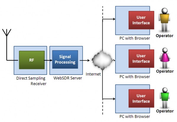
The Direct Sampling Receiver is the RF component. He transforms the RF signal in a digital I/Q stream. The I/Q (seven band) stream is send via Gigabit Ethernet to the WebSDR server. In the case of sufficient bandwidth, the direct sampling receiver could be located anywhere (physical independency).
The WebSDR Server is used as an interface server between the receiver and the user. The server is in charge of the signal processing. The server generates out of the I/Q stream a spectrum view and audio streams for each connected user. Any improvement (e.g. better filters) can be realized by the means of a software update.
The user connects through the web browser to the WebSDR server. The Web browser is the User Interface. The user selects the desired signal on the band with a single mouse click. A few milliseconds later he can hear the signal through his loudspeakers. The user can be located everywhere in the world. There is no geographical / physical dependency between the server and the user (client). There is also no logical dependency. A high number of instances of the User Interface (the persons who are listening) can access at the same time on the same receiver without interfering each other.
Could you imagine such an application a few years ago?
Conclusions
A radio is a big box with a ton of knobs, even more LEDs and occupying the majority of our desks? Yes, that’s still the case. But we are moving – towards an exciting future. Therefore it is crucial to understand the SDR approach. In contrary to the classic radio, the three components (RF, Signal processing and User Interface) of a SDR are independent of each other. This is mainly enabled by interfaces and protocols which have been established as industry standards during the last decade. Powerful semiconductors and broadband Internet allows us the design of a whole new range of applications. With the two presented examples you can see how powerful this technology already is.
Related Posts
written by: Tobias, DH1TW | 4. February 2010