![]()
Last Modified: July 23, 2011
Contents: Basics; Basic Nomenclature; Adding Power; The Impedance Thing; Other Formulas; Pitfalls;
This web site shuns complicated mathematics for a variety of reasons. Yet, there are a few basic math skills one has to have just to be an amateur radio operator. For example, you do need to be able to add, subtract, multiply, and divide. It is also nice to know a few basic formulas, and that is what appears here.
You also need to know the various nomenclature used in the formulas, and those are included too. They are by no means complete, and I refer you to the ARRL Handbook for the complete, and unabridged explanations. By the way, the ARRL Handbook costs about $50 delivered to your door. It is a bargain among bargains considering the wealth of information that lies therein. If you take the time to read it cover-to-cover a couple of times, you'll end up knowing more than 90% of the licensed amateurs!
It should be obvious that what you read here is overly simplified. It is presented in hopes it will spur a few to delve much deeper into the intricacies of amateur radio.
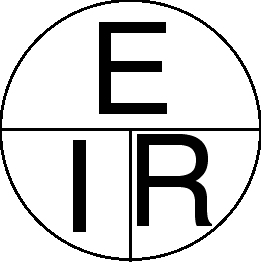 Probably the most used symbols (nomenclature) used in amateur radio are those of Ohm's law:
I = Intensity of current, expressed in Amperes
E = Electromotive force, expressed in Volts
R = Resistance, expressed in Ohms
Almost every calculation you'll do in amateur radio uses at least two of these in the formula, and most have all three! They should be rote to memory, as should the chart at left.
Referring to the chart, whatever the unknown is, you just cover it with your finger, and the correct formula will appear. For example, if we want to know what the current flowing through a circuit, and we know the voltage and the resistance, here's what we do. Remembering that I represents the current in amperes, we cover up the I, and the correct formula appears. In this case, R (resistance) divided into E (volts) gives us I (current). Plugging in real values, if the resistance is 10 ohms, and the voltage is 24, then the current equals 2.4 amperes. If you want to know the voltage, and you have the current and resistance, you just multiply I times R.
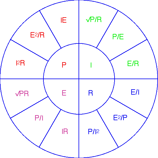 Amateur radio isn't just about volts, current, and resistance. It is also about power! So, lets expand the chart to include power. By the way, clicking on the charts will open them full-sized in a new window, and may be printed if desired.
The new symbol added to this chart is P which stands for power, and is expressed in Watts. Referring to the chart, the unknown is in the inner circle. One of the formulas under the unknown P, is I2R (current squared times resistance). I point this out because the term (I2R) is often used in speech and text to describe (overall) circuit losses. It is especially useful when you're trying to choose the correct sized wire. Here's an example. If you know the resistance of the wire (that's in the ARRL Handbook too), and the current draw of your transceiver (from the User's Manual), you can easily calculate how much power is being dissipated in the wire. Most of the time, it is a lot more than most folks realize.
Also added to the chart is the Square Root function, something most folks don't know how to do on paper. Thankfully, even a cheap $10 calculator has that function nowadays.
 The above formulas work very well at DC, and low frequency AC (up to about 50 kHz). Once the frequency climbs high enough, we start thinking in terms of RF. This requires a whole new set of formulas, and a whole new nomenclature, to say nothing about a whole new scope of understanding. Since the requisite knowledge is beyond basic math, it won't be covered here. Again, the ARRL Handbook is the best place to start. However, we have to be aware of a few of the basics.
Impedance, like resistance, is measured in ohms, and is expressed as Z. However, it is a combination of both resistance and reactance. The resistive portion is the familiar R, and the reactive part is expressed as X. The reactive portion, X, can be capacitive reactive (C), or inductive reactive (L). The reactance in ohms is expressed as -j (lower case) or +j, respectively.
If there is one detail which needs to be emphasized here, it is this: When it comes to antennas, the resonant point is not the lowest SWR, but when X =Ø.
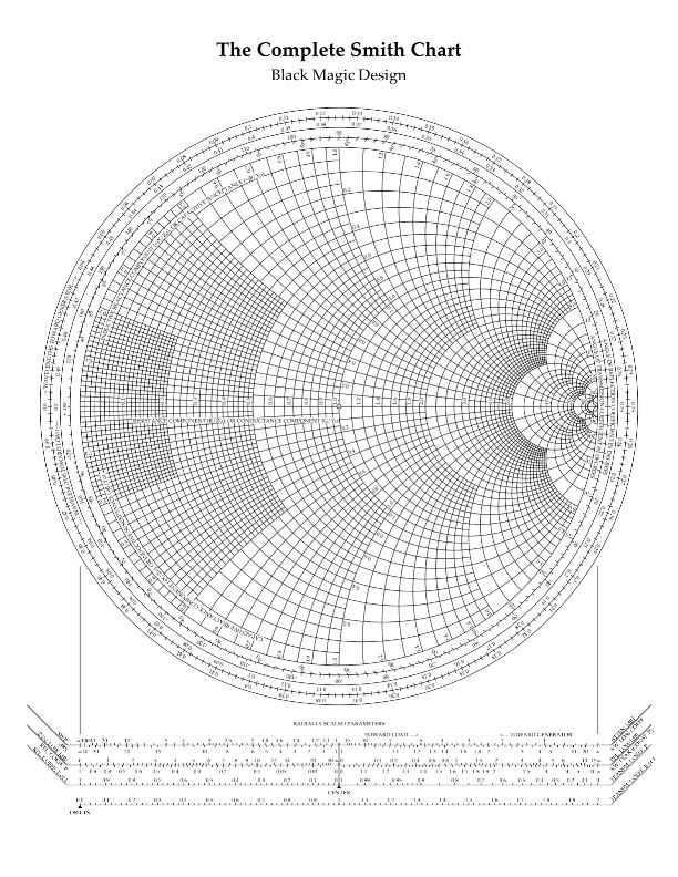
There are also reciprocals of Resistance, Capacitance, and Inductance. They're known as Conductance, Admittance, and Susceptance. They're expressed as G, Y, and B respectively. They're used in complex reactance calculations, and a further explanation is well beyond basic math. I might add, if you teach yourself how to use a Smith Chart®, G, Y, and B are part of the process. Again, the ARRL Handbook is your best source, as there is a whole chapter devoted to just the Smith Chart®. If you want to play with a Smith Chart® on line, here's where to go. You can also download all manner of Smith Charts®, even color ones. Just do a Google search.
There are a few formulas that aren't used much in mobile operation, but are important to know. This is by no means a complete list, but rather ones used most often.
The formula, 234/f (234 divided by the frequency in megahertz) will give you the length, in feet, of a 1/4 wave antenna. However, it isn't exact as it assumes the radiating element is infinitely small. For example, if the radiating element was one inch in diameter, the resonant length would be somewhat shorter than the calculated one the formula gives you. So call it an approximation.
The term SWR (Standing Wave Ratio) is undoubtedly the most misunderstood concept in amateur radio, bar none! There is both a VSWR (voltage) and a CSWR (current), albeit rarely expressed as such. It is nothing more than the ratio of forward vs. reflected voltage, or current as the case may be. It is always the larger figure divided by the smaller figure. For example, if the measured input impedance is 35 ohms, and the line impedance (Z) is 50 ohms, then the resulting SWR would be 50/35 = 1.4:1. This assumes there is no reactive component, and the antenna's impedance is purely resistive; a fact which almost never happens in the real world. Here's another point to remember. In a mobile scenario, when comparing the unmatched input impedance of HF antennas, the one with the highest SWR is the better antenna!
Both inductors and capacitors have a quality factor, expressed as Q. It is the ratio reactance (X), divided by the sum of all of the resistive values making up the energy losses (Q = X/R). As with all RF measurements, R is the resistive losses at the operating frequency. Therefore, Q is not something you can measure with a common DVM (digital voltmeter). While coil Q is important from an HF mobile antenna's efficiency standpoint, once the Q surpasses 350, even doubling the Q has little affect. The reason for this, and the point made in the last paragraph, are explained in my Antenna Efficiency article.
The lowly Decibel is another greatly misunderstood term. It is a logarithmic measurement of relative ratio between two power levels. We use Decibel rather than Bel, as the latter is too large for most uses. By the way, it was named after Alexander Graham Bell, inventor of the telephone. The formula is 10 log (Pout/Pin). For example, if we increase power from 100 watts, to say 300, you get 4.7 dB increase. From 100 watts to 1,000 watts, you get 10 dB.
Remember, it is relative power ratio, so when it is applied to antenna gain, you have to compare it to some known quantity. In the amateur world, that's typically one of two; dBi and dBd. The last letter refers to either an isotropic source (i), and to a reference dipole (d). Several problems crop up with either term. First, there is no such thing as an isotropic source (infinitely small, pin point radiating source). Further, the reference dipole only exists in free space, not down here on earth where we all live. Making matters worse, far too many amateurs assume the difference between the two (dBi and dBd) is ≈2.4 dB. In reality, the difference might be near zero, and it might be nearly 9 dB. It should be obvious that leaving off the descriptor just adds insult to injury.
One result of not understanding what is and isn't a dB, leads a lot of amateurs to play the Gain Game. That is to say, if one antenna's advertised gain is 6 dB, and the competitor's is 3.6 dB, it has got to be better, right? Probably not. In fact, if the first antenna was expressed in dBi, and the second one in dBd, the difference in gain is zip! Unfortunately, too many manufacturers leave the descriptor off, which in essence nullifies their gain claim. Do yourself a favor, avoid this pitfall. And speaking of pitfalls...
There are a few pitfalls to avoid when using formulas, and the measurements that go along with them. To wit, you cannot measure one parameter, and assume it applies to all parameters. This is best explained by examples. One of the most frequent examples is measuring an antenna's bandwidth, say at the 2:1 SWR points, and correlating it to antenna efficiency. This fact is also explained in my Antenna Efficiency article.
As I alluded to above, a low SWR is not a panacea for any antenna woe. In fact, depending on the way you go about achieving one, may indeed increase losses, and thus reduce efficiency. Old timers often refer to this malady as viswaritis. In other words, just because the SWR is low, doesn't mean much if the rest of the parameters (ground loss for example) aren't known.
It seems almost sophomoric to mention this, but DC measurements made with a digital voltmeter, have no relation on any factor relating to RF. This is especially true of ground straps. For some unknown reason, folks think a DC ground is the same as an RF ground, or worse, a ground plane. The often heard phrase is, I have a low resistance ground. What they should say (if they understood the processes), I have a low impedance ground. However, the vernacular change is not the solution, it is the problem! Perhaps this article will help.
This is not strictly math, but it is a good note to close on. An S meter isn't a very good measurement tool, no matter the radio. In fact, in some cases, the readings are not repeatable. I'll give you a good example, but it certainly isn't the only one. Icom's IC-706 and IC-7000 both use the same basic circuitry to measure SWR and forward power; a source for ALC, overdrive, and over temperature; cooling fan control; and the Tuner port signaling. As the radios warm up, the S meter reading for any given incoming signal changes. The point here is, using the S meter as a measuring tool, is like using a hammer as a screwdriver.